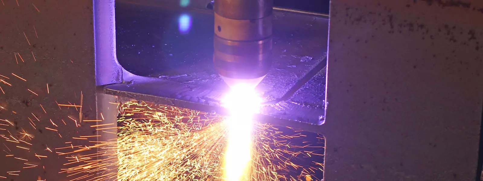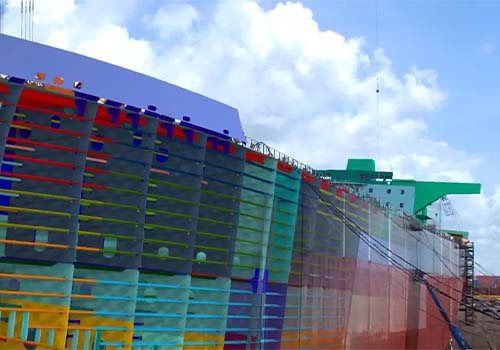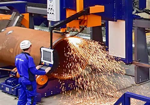
SSI’s integration with HGG make it easy to cut profiles and pipes directly from the digital twin, with almost no effort from the engineering team or the shop floor.
Choosing the right production automation equipment
Automation is one of the most powerful benefits of a digital transformation and results in significant time savings, improved consistency, and makes it easier to adapt to change. Production automation brings those benefits down to the shop floor as it removed the need for the manual programming and setup of each cut.
The production equipment your shipyard chooses needs to support the capabilities your projects require, but it also needs to support automated workflows that allow your production team to directly take advantage of 3D product model data.
HGG’s integration with SSI’s shipbuilding ecosystem results in the seamless exchange from the 3D CAD environment to the CNC profiling machine, without the need to write custom code. Because there is a direct link between the systems, the risk of using out-of-date information is also reduced. The associated labor-hours saved are substantial.

Having an automated process to get information from your 3D product model to your production machines is more efficient not only because it streamlines the process, but also because it actually removes all the tasks which are needed to support the manual process.
Denis Morais, CEO at SSI
HGG and SSI joint shipyard success
Greenbrier Gunderson Marine identified an opportunity to better connect model information with the shop floor by automating production machinery. The team looked at how they could take plate, profile, and pipe information from ShipConstructor and easily transfer that to the HGG cutting and bending machinery on the shop floor. Using the model data in this way was a game-changer, particularly for complex pipe-cutting tasks. It removed the need for a skilled worker to be solely focused on a single cutting or bending task.
Using EnterprisePlatform, Greenbrier easily extracts all the necessary profiles in 3D DXF for nesting. Then, that information is sent to the cutting machine using a pre-configured XML file. The integration removed the need to manually parse the profile data each time the machinery needed to be used. At the same time, the metadata on what panels had what nests was fed to the ERP system, giving the rest of the organization more visibility into production.
What’s supported
Profiles
- Tees
- Bulbs
- Flats
- Angles
Part geometry
- ‘End cuts’ of part ends.
- ‘Cut-outs’ in the web of a profile for crossing profiles.
- ‘Penetrations’ like holes of piping.
- ‘Trim angles’ for basic part detailing by straight lined cuts.
Marking geometry
- ‘Inverse bend lines’ for easy and accurate bending of bulbs;
- ‘Reference marking’ for easy and accurate fitting of parts;
- ‘Part ID’s’ of the part itself or the ID of a connecting part.


