Introduction
I just returned from COMPIT 2015 in Ulrichshusen, Germany. As always, there were a good number of presentations related to the integration of disparate systems (CAD/PLM/PDM/etc…). The topics ranged from a peer-to-peer service based architecture for the integration of various tools into a single virtual ship design platform, to the implementation of an enterprise portal as a single point of access for ERP, CAD and PLM data.
My presentation was focused on a slightly different aspect of information sharing and on integration with one of the ‘softer’ systems in a shipyard: people. People still need to consume engineering data and take direct action based on the information provided. The most obvious case is the delivery of drawings and work packages to the waterfront. Additionally, there are still many situations in a typical shipyard (and with suppliers to the shipyard) where systems and processes are not well integrated (or at all) and people make decisions based on, or enter data from, a multitude of drawings, spreadsheets and other deliverables.
In forward thinking shipyards, especially those dealing with higher costs of labor, we’ve seen an increased investment in areas like production automation and integration between various systems. This has certainly reduced the reliance on drawings as a source of information for other process and tools. However, even in the most advanced shipyards drawings and spreadsheets are still used to communicate.
The Model Based Enterprise and Model Based Definition
In other industries the problem is being addressed in a number of ways. One of those that is getting the most attention is an approach called the Model Based Enterprise (MBE). MBE is an approach predicated upon the idea that the entire enterprise (and lifecycle of the product) should be driven by a single fully annotated 3D product definition.
I won’t spend too much time on the approach in this post. You can find more here or here. Where I will spend some time is in talking about the foundation of an MBE approach: the Model Based Definition (MBD). An MBD is a single package that includes all of the information about the product. This includes the 3D model, annotations, product and manufacturing information (PMI) etc… The goal of the MDB is that it is readable by anyone, anywhere with no barriers to access. This means neutral formats, no proprietary software, and no IT barriers.
In some of the recent MBD implementations, 3D PDF is emerging as a standard. I think there is good reason for this, primarily that your current PDF viewer can likely read 3D PDF’s. I think this format is worth exploring in the future as an MBD for the shipyard. However in this case we wanted to explore an option that could be implemented today with little effort.
MBD for Shipbuilding
In looking at the application of an MBD to the shipbuilding industry we first recognized that there are a number of requirements/challenges that are specific to our industry.
Scale/Complexity
The first goes to the very nature of the ‘product’. For (obvious?) reasons of scale and complexity we can’t package the entire ship into a single MBD. Not only would this be technically infeasible, it would be unwieldy and unusable for a human being. An outstanding question is “What are the most effective packages for the shipyard?” I have some ideas an examples below.
Drawings, Drawings, Drawings
In pretty much any industry that builds something you will hear people complain about the reliance on, and weaknesses of, drawings. The grass is always greener, and they will all compare themselves negatively to other industries. At the risk of sounding like “me too”, I will say that shipbuilding is more reliant on drawings than any of those other industries.
Any solution that would be usable in many shipyards today needs to fit the way drawings are created, and needs to fit the way drawings are consumed.
Potential Solutions
We explored a number of options, from Navisworks models, to plain AutoCAD DWG but all of the options left a little bit to be desired. However, Autodesk has a format that fits many of the requirements of a MBD already: the Autodesk Drawing Web Format (DWF).
Why DWF?
For now, I really like the application of DWF for the creation of an MBD because it seamlessly works with ShipConstructor without a lot of change to existing tools, processes and workflows.
Non-Disruptive to Engineering
First and foremost, because ShipConstructor drawings (like any AutoCAD drawing) contain both a layout with the 3D model and layouts for each deliverable drawing they can be effortlessly turned into DWF files that contain the 3D model and those drawings. When the drawing is plotted (whether it is to end up in a PDM/PLM system, a paper work package or simply to a file folder), the PUBLISH command can be run to create the DWF as well.
Drawings Still Key
As the process would be created from drawings, and drawings would be a key portion of the deliverable in the package, individuals who currently consume PDF’s or other representations of the drawings can now consume the DWF file instead (or as well).
Fully Compatible with ShipConstructor
As this process is initiated from ShipConstructor/AutoCAD the 3D model contained in the DWF includes all of the PMI included in the ShipConstructor model and drawings.
‘Neutral’ Format and Viewers
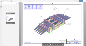
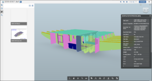
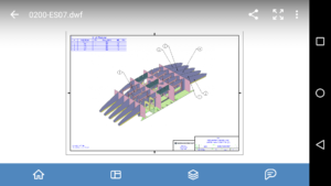
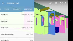
While the DWF format isn’t technically a neutral format (in that it isn’t a recognized standard) it does approximate one both because it is an Autodesk format (due to Autodesk’s position in the CAD market space you will find add-ins for other CAD products to export DWF etc…), and because of the multitude of free and simple viewers for DWF. Check out the video below for a view of the desktop viewer (Autodesk Design Review) in action with ShipConstructor. In addition both mobile and web (cloud) based viewers are available:


How it is Done
The easiest way to implement this, as shown in this video, is to simply run the PUBLISH command within any ShipConstructor drawing. Other than ensuring that the 3D DWF option is selected for the Model layout there are no additional steps required here.
Of course this is for the simplest possible case where a single ShipConstructor drawing contains the entire ‘product’ you want to capture in your MBD package. This might cover a decent number of use cases. However, I think the real power will come from adding additional layouts and models from other drawings to the package. Here are some possible scenarios:
- A pipe arrangement, system model, and all spool drawings for that system.
- A model of a structural block and all class approval drawings for the block as a class package.
- A model of a structural block and all assembly drawings for the block.
During the PUBLISH command layouts from other drawings can be added. I had planned to create some of the scenarios outlined above for this post. If I do create those later I will update them here.
The Future
Two (connected) areas of this that warrant further exploration are whether these can be easily generated by EnterprisePlatform PublisherLT and how this integrates with AutoCAD Sheet Sets (SC 2015 R2 revealed new Sheet Set Manager capability – via the Subscription Advantage Pack). Neither of these has been explored in detail but they are connected. The command-line version of the PUBLISH command takes a Drawing Set Descriptions (DSD) file that can be exported from the Sheet Set Manager.
Conclusions
In most shipyards, the drawing (along with the venerable spreadsheet) still is the defacto standard for communication of engineering information to people who need it. Using existing engineering processes and tools, a 3D DWF Model Based Definition can provide a non-disruptive yet powerful alternative. This approach requires very little implementation, no additional software purchases, and is a bridge to newer technology that does not yet abandon drawings. I’d be interested to hear your thoughts.

Post Comments
Can this work with MarineDrafting 2D drawings?
Yes Mark, the 2nd example I mentioned above (model of block and class drawings) is exactly that case. The combination of the 2D layouts from a MarineDrafting drawing and the model from the Output drawing, in a single package, could be very compelling.
Are the SC item properties included in the DWF when you publish a MD 2-d drawing?
Hi Erik, the answer is yes and no. The DWF includes the 3D model that is in model space and that includes a complete property set. The 2D geometry in model space and the Layout do not have properties. This is just the way Publish works with any object including ShipConstructor.