The Hull team at Albacore Research Ltd. (ARL) is providing users with new functions in ShipConstructor2005’s Hull module this fall. Working inside of AutoCAD gives the Hull team powerful new tools to develop easy-to-use functions for previously complex tasks.
The Hull team at Albacore Research Ltd. (ARL) is providing users with new functions in ShipConstructor2005’s Hull module this fall. Working inside of AutoCAD gives the Hull team powerful new tools to develop easy-to-use functions for previously complex tasks. The list of features for the scheduled October release include:
- NURBS- curve fairing (Nudging)
- Curvature colour display and ISO lines
- Forward/backward surface mapping (Markline synchronizing)
- Shell expansion
- Deck surface generation
- Generation of developable and curved surfaces from NURBS-curves
- Freeform rail extruded surface generation
- Plate expansion strain as ISO lines
- Stringers creation using girthing function
- Import/Export IDF, export GHS
- Additional 2D forming template options
- Bow fashion template by number of templates
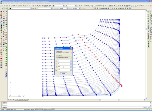
NURBS-curve Fairing (Nudging)
As a lead into a transfer of all fairing functions from ShipCAM to Hull, this new version offers the ability to fair curves inside of AutoCAD and generate developable and double-curved surfaces from the faired curves. You can move control points individually or select any number and move them in unison.
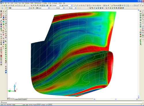
Curvature Colour Display and ISO Lines
A curvature display creates new opportunities to increase product quality, simplify construction and save man hours. The curvature display comes in two forms: colour coded display and curvature ISO lines – lines of constant curvature. Use this function to detect and eliminate unfairness in any surface or mark problem areas for the forming of highly curved shell plate.
Forward/Backward Surface Mapping
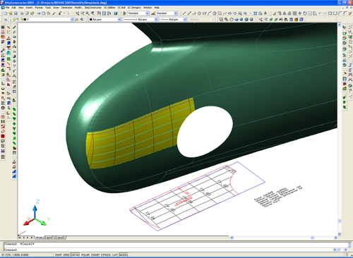
Occasionally, plate expansion and plate forming involves difficult plates that can cost thousands of dollars of wasted time and material. ShipConstructor now adds tools that enable users to simplify these difficult cases. In the following examples we show two typical scenarios.
First, the forward upper end of the plate (at right) contains curvature that is beyond the established threshold for easy plate forming. The shop has to be informed about this problem area. In this case the curvature ISO line (red) is selected and mapped from the 3D plate to the 2D expanded plate.
In the second scenario, you will find a blue rectangle, defining the maximum plate size, overlaid onto the expanded 2D plate. As you can see, the expanded plate is too large. Now it is as simple as selecting ‘Synchronize Plates’ from the context menu to transfer the maximum 2D size back to the 3D hull surface for re-trimming.