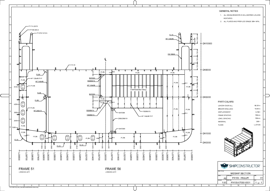
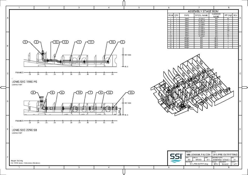
Consistent outputs rely on consistent inputs from designers and predetermined formats that pull information whenever possible from the common product model, minimizing human error.
In Part 1 we reviewed the impacts of non-standardized deliverables beginning with part creation, through modeling, drawing deliverables, change management, and the effects on downstream processes such as PLM and ERP systems. Taking the time to create a process for designers quickly improves the efficiency and quality of the model and drawing outputs and mitigates those same impacts.
Determine the standard
Producing standardized, consistent documents begins by determining what the standard is. While standards may be known, it is important to check in with all the stakeholders periodically to ensure organizational requirements are consistently met. To determine if engineering deliverables are fit for purpose, here are some questions to ask:
| Questions | Example |
| Are the drawings fit for purpose? | If the drawing is an assembly drawing, it should contain only assembly drawing details. Fabrication (part cut) and installation (ship measurement) details should be shown on other drawings. |
| Do drawings contain all the information required? | Ensure no measurements or details required are missing. Ensure no critical details can be misinterpreted. |
| Are there any legacy requirements that can be removed? | Not long ago, every panel needed to be dimensioned. Nowadays, machines etch the mold lines of connecting plates and profiles onto plates, and only a few overall dimensions are required. It is not uncommon to see legacy requirements like this still being incorporated into drawings. |
| Do drawing BOMs contain the right information? | The product model could reference 50+ database attributes. To keep drawings easy to use, ensure only the relevant properties are shown. |
A team’s efficiency must not sacrifice organizational efficiency. An engineering department may be able to churn out drawings, but if their efficiency creates more work downstream, the organization suffers. For example, production departments may manually determine missing dimensions, add production markings, and break spools down further for access and removal. All these things can quickly or automatically be added by the engineering teams.
It starts with catalog creation
Efficient, repeatable deliverables begin with consistent stock catalog entries. Creating acceptance criteria for designers ensures part data is added correctly to meet organization requirements. For example, adding an equipment part:
| Equipment Library Acceptance Criteria | Check |
| The equipment has a name consistent with internal standards | |
| The equipment has at least one insertion point added | |
| The equipment has all connections added Piping HVAC Electrical | |
| The equipment has a valid weight defined | |
| The equipment has required accessory packages added | |
| The equipment 3D model has been optimized to be lightweight (using shrinkwrap in Inventor or similar) | |
| The equipment has required maintenance and shock envelopes defined | |
| The equipment geometry is on the required layer | |
| Required user-defined attributes (UDAs) are added | |
| The equipment is inserted into the PEL (Project Equipment List) and assigned stock |
Modeling Requirements
Continuing with the example of equipment, the following acceptance criteria should be met when placing equipment in the common product model.
| Equipment Modelling Acceptance Criteria | Why? | Check |
| The equipment items are valid, inserted from the catalog, not ‘dumb solids.’ | ‘Dumb solids’ can be quick to create but do not contain the metadata to create an intelligent model – inaccurate weight, no parametric relationships, no BOM data, etc. | |
| The equipment connections (Pipe, HVAC, and Electrical) are connected to something | Connecting interfacing equipment creates a parametric model and ensures only valid parts can be connected. | |
| The equipment items use an auto-generated part name | Consistent naming of all parts | |
| The equipment is placed within the appropriate drawing/model | Equipment should be placed in the system it belongs, e.g., a pump should be placed within the pipe system it belongs to for quick referencing | |
| The equipment is assigned to the work breakdown structure (assembly) | For visualization and drawing generation, equipment needs to be placed in the appropriate assembly sequence |
Bridging the experience gap between designers
Experienced designers, through their time at the shipyard, or designers with trade backgrounds, think practically about producibility and installation. Creating a checklist for designers helps bridge the gap by leveraging the experience of others. Here are some examples of acceptance criteria when inserting equipment into the design and creating drawing outputs.
| Equipment location checklist | Check |
| Have foundations been allowed for (if applicable) | |
| Have shock mounts been allowed for (if applicable) | |
| Has clash detection been run | |
| Have maintenance envelopes checked (If applicable) | |
| Is the equipment placed in the maintenance/operation space of other equipment | |
| Can the bolts be tightened (Can you get hands and tools to the bolt holes) | |
| Can a welder reach the required location | |
| If deck mounted, can water drain around it |
| Equipment drawing output checklist | Check |
| Is there measurements locating the equipment on foundations | |
| Do mounting holes need to be templated and cut on-site | |
| Can the measurements be measured on-site with a tape measure (Not to refer to a place like a ship centreline) | |
| Do the measurements account for material thicknesses |
Templates drive repeatable drawing outputs
Templates for each deliverable type can be created, with pre-configured information, ensuring repeatable deliverables. Templates for each drawing type require title blocks pre-filled with database-generated information. Drawing views should be pre-configured with appropriate BOMs, display styles, label styles, and drawing views.
Further to drawing generation – consistent text, leader, dimension, line weights, and line type standards conforming with international, local, and defense standards should all be considered.


| Drawing template checklist | Check |
| Preconfigured styles (dimensions, annotations, leaders, balloons, BOMs) | |
| Preconfigured title block populated from database values | |
| Preconfigured layers, layer styles (Line weights, colors) and layer states | |
| Preconfigured display styles for each drawing type | |
| Preconfigured label styles for labeling views with database values rather than manual notes |
Conclusion
Standardized, repeatable deliverables are critical to an organization’s success. The effects of inconsistent data can last decades. Creating a process for designers is a great way to improve both team and organizational efficiency. In short, to achieve success with standardized deliverables:
- Regularly review deliverable requirements.
- Create Acceptance Criteria for designers to ensure consistent model inputs.
- Bridge the gap between different designer skills with a checklist.
- Automate repetitive tasks and processes with quality templates for each drawing type.
