In today’s modern shipbuilding it is common for us to receive several different types of CAD files. There are various valid reasons for this such as:
- The suppliers provide CAD formats in their native application or a “standard” (STEP, IGES, DWG, STL, SAT, IFC, etc.).
- The owner/client supplies files used for reference.
- A subcontractor supplies their deliverable in a non-native CAD format that is different from what you use internally.
- Your prime has provided reference geometry in a specific CAD format.
- You have old designs in a different CAD format than what you use today
- You are doing a repair or maintenance job so you get various different formats.
- Many many more.
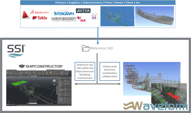
No matter what the valid reason is, you will need to somehow be able to leverage the information in the other CAD formats to complete your task. Having your native CAD environment able to consume various different CAD formats will allow you to streamline your workflow no matter what CAD format you receive.
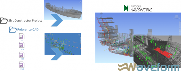
In this post I will show you how the SSI (ShipConstructor) engineering hub environment will aid you in leveraging over 30 different CAD formats. This should handle the majority of formats that are used within the shipbuilding industry. I will show you how to reference virtually any CAD within ShipConstructor while modeling native ShipConstructor parts. I will also show how to identify clashes between ShipConstructor and the other CAD files.
FYI: A list of file formats and a video demonstration is found at the end of the blog post.
Overview
Since ShipConstructor 2016 we have had the capability to reference various different types of CAD files using the coordination model feature. I have demonstrated it once before in the blog post: ShipConstructor Tips & Tricks: Referencing Parts. However, in that blog post I focused on showing how you would be able to reference an entire ship within the ShipConstructor environment. It was not very practical, but it was to show that there is no limit in the number of items you wanted to display in ShipConstructor.
The workflow is similar when using other non-native CAD formats.
Setup
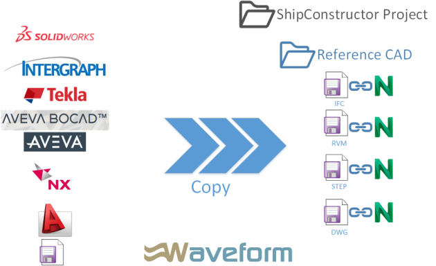
There is no restriction on where you store your CAD files as long as you have access to them. However, to simplify management and access for your ShipConstructor users it probably makes sense to store your CAD files in a folder under the ShipConstructor project. Let’s call it Reference CAD. You can organize your files with any names as well as any level of folder structure.
Then, using Navisworks batch utility, you can automatically create NWD/NWC for each of your files. If you have not done this before you can refer To Convert Multiple Design Files into Individual NWD Files.
In ShipConstructor
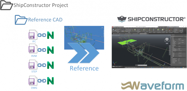
In ShipConstructor you can be in any drawing and reference any of the CAD files by using command COORDINATIONMODELATTACH. Before running the command, you may need to be in world coordinate system to ensure that your models align. When you run the command, you will be asked to select one of the Navisworks files generated in the previous step. That is, it.
In ShipConstructor the CAD file is referenced so you will not be able to modify it. However, you will be able to snap to the geometry which can be a significant help. There are some visualization settings which you can use to ensure you do not confuse what is in the CAD file and what is native to ShipConstructor.
Unified Coordination View with Global Clash Management
Most of the time when we get CAD formats from other partners or subcontractors we need to put them all together to verify there are no clashes. The best strategy for this is to leverage Navisworks which is the industry standard for supporting all major CAD formats and has the most capable clash management environment.
The strategy that most use is to create a ShipConstructor Navisworks NWF for the entire project using PublisherLT. Then, you would open the Navisworks NWF file and append the other CAD files, then save.
With this strategy the NWF will always pull the latest version of your CAD files. So, if you receive an updated version of the CAD file, you can simply replace it in the Reference CAD folder, and the next time you open the Navisworks file it will display the updated information.
As mentioned, you can do clashes in Navisworks which I will not go into detail here as I have several blogs about clash management with Navisworks. However, I will mention that once a clash is found you will be able to switch back to ShipConstructor with a click of a button with the same view direction in Navisworks to allow you to make any changes in ShipConstructor. Once the changes are done in ShipConstructor they will refresh in Navisworks after you click the refresh button.
Video Demonstration
Demonstration of all steps mentioned above:
If you do not have access to the YouTube you can access the video on SSI Nexus here
File Formats Supported
| Format | Extension | File Format Version |
| Navisworks | .nwd .nwf .nwc | All versions |
| AutoCAD | .dwg, .dxf | Up to AutoCAD 2017 |
| MicroStation (SE, J, V8 & XM) | .dgn .prp .prw | v7, v8 |
| 3D Studio | .3ds .prj | Up to Autodesk 3ds Max 2017 |
| ACIS SAT | .sat .sab | All ASM SAT. Up to ACIS SAT v7 |
| Catia | .model .session .exp .dlv3 .CATPart .CATProduct .cgr | V4, v5 |
| CIS/2 | .stp | STRUCTURAL_FRAME_SCHEMA |
| DWF/DWFx | .dwf .dwfx | All previous versions |
| FBX | .fbx | FBX SDK 2017.0 |
| IFC | .ifc | IFC2X_PLATFORM, IFC2X_FINAL, IFC2X2_FINAL, IFC2X3, IFC4 |
| IGES | .igs .iges | All versions |
| Inventor | .ipt .iam .ipj | Up to Inventor 2017 |
| Informatix MicroGDS | .man .cv7 | v10 |
| JT Open | .jt | Up to 10.0 |
| NX | .prt | Up to 9.0 |
| PDS Design Review | .dri | Legacy file format. Support up to 2007. |
| Parasolids | .x_b | Up to schema 26 |
| Pro/ENGINEER | .prt .asm .g .neu | Wildfire 5.0, Creo Parametric 1.0-3.0 |
| RVM | .rvm | Up to 12.0 SP5 |
| Revit | .rvt | Up to 2017 |
| SketchUp | .skp | v5 up to 2016 |
| Solidworks | .prt .sldprt .asm .sldasm | 2001 Plus-2015 |
| STEP | .stp .step | AP214, AP203E3, AP242 |
| STL | .stl | Binary only |
| VRML | .wrl .wrz | VRML1, VRML2 |
| All versions | ||
| Rhino | .3dm | Up to 5.0 |
| Autodesk ReCap | .rcs .rcp | |
| ASCII Laser File | .asc .txt | n/a |
| Faro | .fls .fws .iQscan .iQmod .iQwsp | FARO SDK 5.5 |
| Leica | .pts .ptx | n/a |
| Riegl | .3dd | Version 3.5 or higher |
| Trimble | Native file NOT supported. Convert to ASCII laser file | Same as ASCII laser file |
| Z+F | .zfc .zfs | SDK version 2.2.1.0 |
Post Comments
This was a nice information. Thank you. I was wondering if there is a tool which can take in pdf drawings of ships and converts it in to 3D models.
There is not a tool that does it automatically that I know of. There are several tools that can be used to create a 3D model from the PDF’s relatively easily. The amount of work depends on the quality of the PDF’s. The higher quality PDF’s can be imported into the ShipConstructor environment and will create the geometry to lines, arcs, polylines. These then can be used to easily create the 3D parts. This process does take a bit of time, but much faster than the alternative. When the PDF’s are of lower quality then the import conversion to geometry is not as accurate and may create multiple lines when only one is needed. There is a bit more clean up needed in these cases.
great information. Thanks.
do you know what the work flow would be to export a ShipConstructor model out to another CAD system to use as reference geometry.
Could this also be done using NavisWorks?
in my situation i want to export a ShipConstructor model into Solidworks,
Then import the Solidworks model back into ShipConstructor,
Then use the solidworks data to modify the Shipconstructor geometry to suit the Solidworks model. (mainly add penetrations round solidworks pipework to be specific .)
Hi Andrew,
Thanks for the great question.
It appears that Solidworks supports DWG, DXF and STEP, each of which is possible to generate from ShipConstructor. If your project has been upgraded for use with EnterprisePlatform, there are operations that can automate the export, in an automated manner, of any selected drawings in your project in these formats (e.g. using Publisher or PublisherLT). It is also possible to use the SCEXPORTDWG command to export a ShipConstructor drawing to a native AutoCAD drawing that can be read by any external applications supporting DWG. This could then be imported/read by Solidworks. If you want to take it a step further and generate STEP files, you can use the STEPOUT command in AutoCAD Mechanical to convert this exported native AutoCAD drawing to STEP.
To reference the Solidworks model inside ShipConstructor, your best option would probably be to generate a DWG from Solidworks, which you could then reference in either Navisworks, or in ShipConstructor itself using the Model Link External command (SCMLINKEXT).
Feel welcome to join us on the SSI Nexus community if you have any other questions!
https://ssicloud.sharepoint.com/sites/nexus/community/Pages/SSI-Community.aspx
Best regards,
Jason Rancourt
Client Success Specialist