Managing welds for ships and offshore structure is typically a disconnected and laborious process in many organizations. I talked about this in a previous post Rethinking Weld Management. The current workflow usually starts off with defining weld paths manually, which takes many man hours. This effort is also very error prone due to the fact that the manual effort does not create or use information from the 3D product model so when changes happen, extra work is required to maintain the manual effort. This continues through the whole workflow when standards need to be defined per weld path to the validation of the current progress of application of welds on the shop floor.
In my last travels I visited several clients who were very interested in improving their entire process of managing welds. The majority of the clients were expanding their business into the offshore market which requires stricter requirements in managing welds and the shipyards‘ current procedures would not satisfy those requirements unless a significant amount of extra effort was introduced.
When I demonstrated ShipConstructor’s WeldManagement product and how it supports a true concurrent environment, leveraging all the information in the MIM (Marine Information Model) in a visual way, they got very excited. The WeldManagement product has various workflows. This allows all stakeholders (Engineer, Designer, Shop floor, Surveyor, Inspector, Project Manager, etc.) to work with data in a multiple ways depending on the user’s skills and task they are accomplishing.
In this blog I will focus only on one workflow to keep this blog post at a reasonable length. The use case I want to focus on is when an Inspector or Project Manager wants to determine the progress of welds of the ship or offshore structure that is being built. What I mean when I say progress is in essence to answer these questions:
- Identify welds that have been welded
- Identify welds that have not yet been welded
- Identify welds that have been inspected
- Identify welds that have passed inspection
- Identify welds that have failed inspection
Typically, to determine the weld progress one would have to look at numerous pages of weld reports from the inspectors and consolidate all the information mentally. This method of determining the weld progress is very time consuming and requires a lot of effort to collect, merge and process the information that is provided.
With ShipConstructor’s Weld Management product the process of determining the progress of welds is much more efficient and requires much less mental effort from the user. The main reason is that it communicates this information visually rather than using pages of text via reports or Excel.
Compare the two versions below.
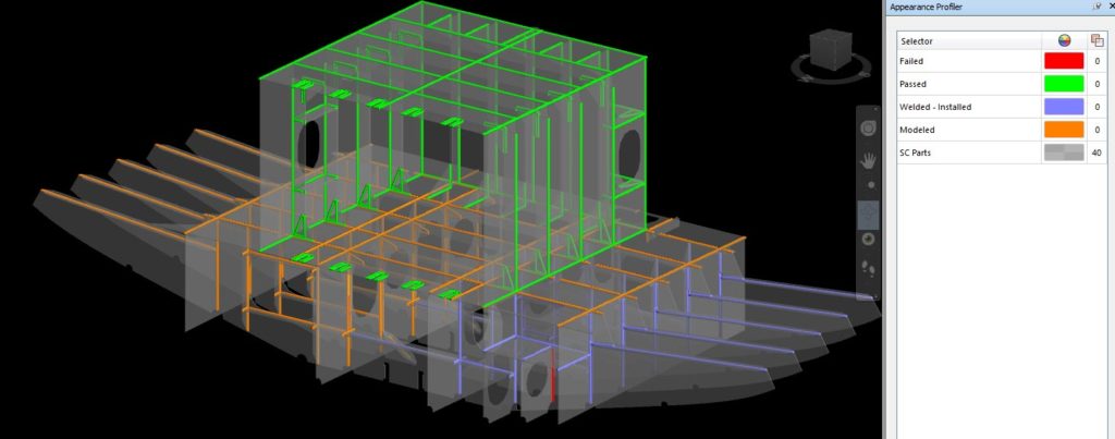
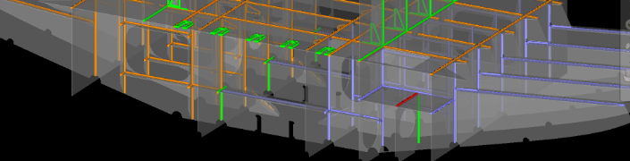
Interactive visual method 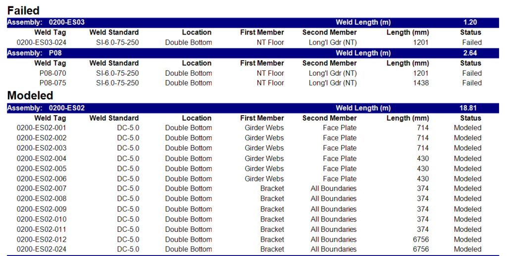
Using traditional reports
The text report on the right will require about 10 pages to illustrate the same information displayed visually on the left. The information of the weld status using the visual method communicates the data in an intuitive and very easily consumable format when compared to the textual report method.
Workflow
Some might think that creating a visual representation of the weld progress requires special skills. However, with ShipConstructor extending the AutoCAD foundation, it really makes the process very easy so anyone, even with no CAD experience, can create this visual representation model.
- Using Autodesk Navisworks you will need to open a WeldManagement drawing already created in ShipConstructor. This drawing contains all the information related to weld which is contained in ShipConstructor and which always reflects the current and most up-to-date information contained in the MIM. This means that there is no extra management from outside the engineering team to ensure the drawing is up-to-date.
- This step is only required for the very first time you are creating this visual model. You will need to import preconfigured selection sets and appearances for how you want the welds to be displayed. The configuration files to be imported are yard specific and can be used for the entire project. This means that there are no specific configuration files for the area you are viewing.
- Run the appearance profile imported from the previous step. This will color code the weld information within your model to what was specified in the configuration files.
- Save the model as an .nwf
- Navigate around the model to view the up-to-date progress
That is it, really. When you want to view the weld progress and you already went through the above procedures, all you need to do is:
- Open the .nwf file you saved in the previous workflow. Opening the file will automatically update the model with the latest weld and geometry information.
- Navigate around the model to view the up-to-date progress.
It is that easy ? Here is a video which goes through the workflow mentioned in this post
Closing remarks
Managing welds in your project does not have to be a disconnected and manual process. There are much better ways to include welds in your design allowing many additional and downstream benefits for managing welds.
Being able to create visually rich representations of the current progress of welds can significantly reduce the amount of effort required to analyze the current weld state. These visual representations can be created by virtually anyone in your organization without ShipConstructor knowledge or an additional license. These models do not technically show more information than the traditional text reports. However, they communicate information much more efficiently, thus allowing you to identify issues as early as possible with much less effort.